Use a multimeter to check ignition coils, wires, and sensors by comparing resistance and voltage to the vehicle service specs. A reading outside spec, or no signal at the component, is a fault flag. Ignoring a weak ignition part can keep a misfire, damage the catalytic converter, and waste time on parts swapping. This guide walks you through a step-by-step meter sequence and a yes/no decision tree to isolate the bad ignition component at home.
How a multimeter fits ignition diagnosis
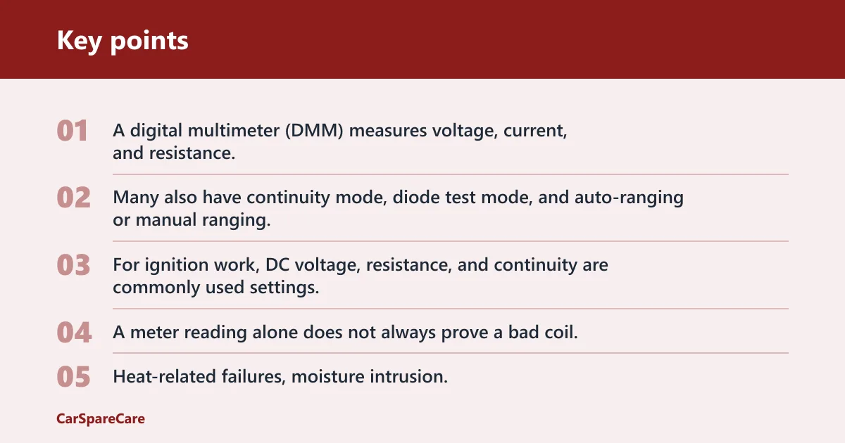


A digital multimeter (DMM) measures voltage, current, and resistance. Many also have continuity mode, diode test mode, and auto-ranging or manual ranging, and some can read capacitance, frequency, and temperature. For ignition work, DC voltage, resistance, and continuity are commonly used settings.
A meter reading alone does not always prove a bad coil. Heat-related failures, moisture intrusion, and weak boots can hide until the engine is hot or loaded, so a coil that looks fine at rest can still misfire on the road. A basic DMM also may not reliably confirm the PCM coil-control pulse on many modern systems.
Start with symptoms that point to ignition. Misfires, rough idle, hesitation during acceleration, poor fuel economy, and hard starting fit a weak ignition coil. A cylinder misfire code helps you narrow the test to one coil, one plug, one boot, or one wire path instead of guessing.
What you’ll need
- Digital multimeter with DC voltage, resistance, and continuity modes
- Backprobe leads or sharp meter probes
- Basic hand tools to reach the coils, plugs, and boots
- Owner’s manual or service data for your vehicle
- Gloves and eye protection
- Flashlight for connector and boot inspection
Ignition test worksheet
| Check | Pass | Fail | What to do next |
|---|---|---|---|
| Battery baseline | About 12 volts at rest; stable during crank | Low or unstable supply voltage | Charge or test the battery and retest before touching the coil |
| Coil connector power | Battery-level feed at the power terminal when the system is awake | No feed or a weak feed | Inspect fuse, relay, wiring, and ignition switch feed path |
| Ground continuity | Continuity to chassis ground or a clear low-resistance ground path | Open circuit or unstable continuity | Clean the ground point, repair wiring, then retest |
| Coil resistance or continuity | Within service-data range, or no open circuit where continuity is expected | Open, shorted, or far outside spec | Inspect the coil, then decide on replacement or swap test |
| Final branch | Meter checks pass but symptoms remain | Single-cylinder fault follows the part | Inspect plug, boot, wiring, or swap the coil to confirm |
How do you check battery voltage first?
Set the meter to DC voltage. Put the black probe on battery negative or a clean ground point, then touch the red probe to battery positive. A healthy 12-volt vehicle system should show a stable baseline before cranking, then stay in a usable range while cranking. Low battery voltage can skew every later reading.
- Turn the DMM to DC volts.
- Put the black probe on battery negative or a clean chassis ground.
- Touch the red probe to battery positive.
- Record the resting voltage.
- Have an assistant crank the engine and watch for a sharp drop.
If a misfire complaint starts after an overnight sit and the battery reads weak at rest, fix the battery or charging issue first. A weak supply can make a good ignition part look guilty.
How do you test the coil power and ground?
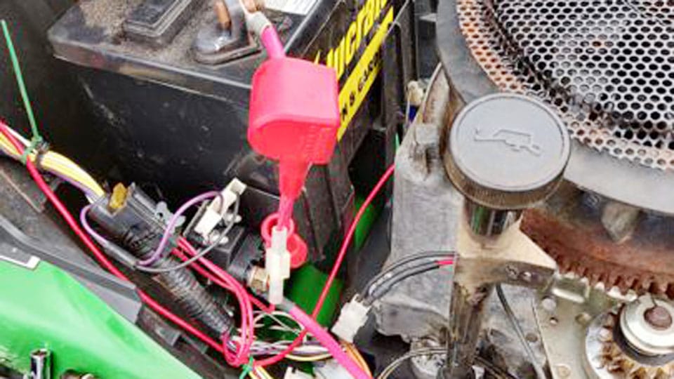
Use the black probe on a ground point and the red probe on the coil connector power terminal. With the key on or during cranking, depending on the system design, you should usually see battery-level feed voltage at the power side. Then check the ground side for continuity to chassis or battery negative.
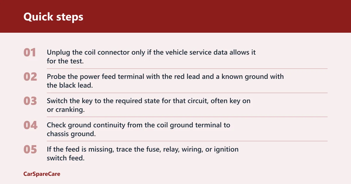
- Unplug the coil connector only if the vehicle service data allows it for the test.
- Probe the power feed terminal with the red lead and a known ground with the black lead.
- Switch the key to the required state for that circuit, often key on or cranking.
- Check ground continuity from the coil ground terminal to chassis ground.
- If the feed is missing, trace the fuse, relay, wiring, or ignition switch feed.
What voltage should an ignition switch read on a multimeter? In the guide example, around 12 volts is expected on the feed side. On some vehicles, access is behind the steering column cover, so follow the vehicle manual before removing trim.
Say your scan shows a single-cylinder misfire on cylinder 3 and the coil connector has power, but the ground path is erratic. That points you toward the ground circuit, not the coil body itself.
How do you test coil resistance and continuity?
Check primary or secondary resistance only if that coil design uses published resistance specs. Continuity mode helps with obvious open circuits in related wiring, but it does not prove the coil can fire under load.
- Key off the vehicle and disconnect the coil if the service data says to do so.
- Set the meter to resistance or continuity, as the test requires.
- Measure between the specified coil terminals only.
- Compare the reading with the service data for that exact engine.
- Repeat the test after the engine heats up if the fault appears hot.
Heat and moisture can make a coil fail only after it reaches operating temperature. If the meter reading is “in range” cold but the misfire returns hot, move to a swap test instead of assuming the coil is good.
How do you read plugs, boots, and wiring next?
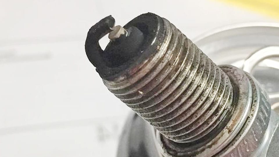
Use the misfire code to narrow the cylinder, then inspect the spark plug, coil boot, and nearby wiring. Weak ignition can leave fouling clues on the plug. Check the plug gap and condition, then look for oil or fuel deposits, heavy wear, or a damaged insulator. A tired plug can point back to a weak spark path.
- Pull the suspect plug only after the engine cools.
- Inspect for fouling, worn electrodes, and abnormal gap.
- Remove the coil boot and check for tears, cracks, brittleness, carbon tracking, and corrosion on the spring or contact.
- Inspect the harness for rubbed insulation, loose pins, or oil contamination.
- If the same cylinder still misfires, swap the coil with another cylinder and see whether the misfire code follows the coil.
A coil-on-plug engine and a coil-pack engine can fail in different ways, but the inspection logic is the same: power, ground, coil condition, then plug and boot. Older wire-based setups add the plug wire to the same inspection chain.
Use the meter in a common order: battery baseline, coil feed, ground, resistance, then component inspection. This sequence keeps you from chasing a bad coil when the real problem is low system voltage, a poor ground point, or a damaged boot. It also gives you a yes/no branch for the next step.
- Check battery voltage first.
- Check coil power feed with the correct key state.
- Check coil resistance only if the design allows it.
- Inspect the plug, boot, and wiring.
- Swap the coil if the fault stays on one cylinder.
A common mistake is assuming the ignition coil is fine just because the battery shows full voltage, without checking resistance and output at the coil terminals. A coil can still fail under heat, and a plug boot can leak spark even when the feed and ground test clean.
Common mistakes
- Using the wrong meter mode. DC volts is not the same as resistance or continuity.
- Testing on a dirty ground point. Use clean metal on the chassis or battery negative.
- Trusting one cold reading on a part that may fail hot.
- Assuming a missing control pulse proves the coil is bad. A basic DMM may not read that signal reliably.
- Skipping the visual check for cracked boots, carbon tracking, and corroded contacts.
- Not checking the plug gap and condition when a misfire code points to one cylinder.
If that didn’t work, try this next
If the meter checks pass and the misfire stays on one cylinder, move to a swap test. Move the coil to another cylinder and clear the code. If the misfire follows the coil, the coil is the likely fault. If it stays with the cylinder, inspect the plug, boot, or wiring next.
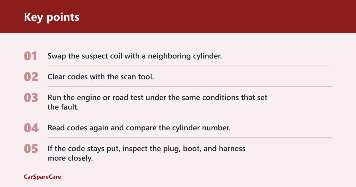
- Swap the suspect coil with a neighboring cylinder.
- Clear codes with the scan tool.
- Run the engine or road test under the same conditions that set the fault.
- Read codes again and compare the cylinder number.
- If the code stays put, inspect the plug, boot, and harness more closely.
A basic DMM is useful, but it is not the last word. For a borderline or intermittent fault, use scan data and a swap test together rather than treating one meter number as final proof.
Frequently asked questions
How do you check continuity on ignition wiring?
Turn the key off, isolate the wire or connector, and use continuity mode between both ends of the circuit. A good wire should show a clear path, while an open circuit points to a break or bad connection. Move the harness while testing if the fault is intermittent.
How do you tell if an ignition coil is bad with a multimeter?
Check for battery-level power, a solid ground, and a resistance reading that matches the service data. If the coil passes cold but the misfire returns hot, heat-related failure is still possible. A coil swap test is the cleanest next step when the meter result is borderline.
What voltage should an ignition switch read on a multimeter
In the guide example, around 12 volts is expected on the feed side. Use the black probe on a ground point and the red probe on the switch output or feed terminal, and check the key position the vehicle requires. Access may be behind the steering column cover.

Hi, I’m Melvin, an automobile engineer with extensive experience in automobile equipment. I currently work for a local automobile firm, where I specialize in the car parts industry. I’ve had the opportunity to collaborate with seasoned inspectors, gaining invaluable hands-on experience that goes beyond just theory.
My passion for automotive care started at a young age, which led me to create CarSpareCare. Through CarSpareCare, I share the knowledge and skills I’ve acquired over the years to help others navigate the world of car maintenance and repairs.
My goal is to provide practical tutorials, essential safety advice, and the latest industry insights so that anyone—whether a beginner or an expert—can confidently tackle their automotive projects.